
Getting to know the hydraulic elements in the hydraulic circuit
You must be faced with various hydraulic maps that are sometimes simple and sometimes complicated, and sometimes you are even confused! No need to worry! Knowing the hydraulic symbols can definitely simplify the complexity of these maps for you and give you the power of analysis. In this part of the series of educational articles of Hydroasma, you will learn more about hydraulic symbols:
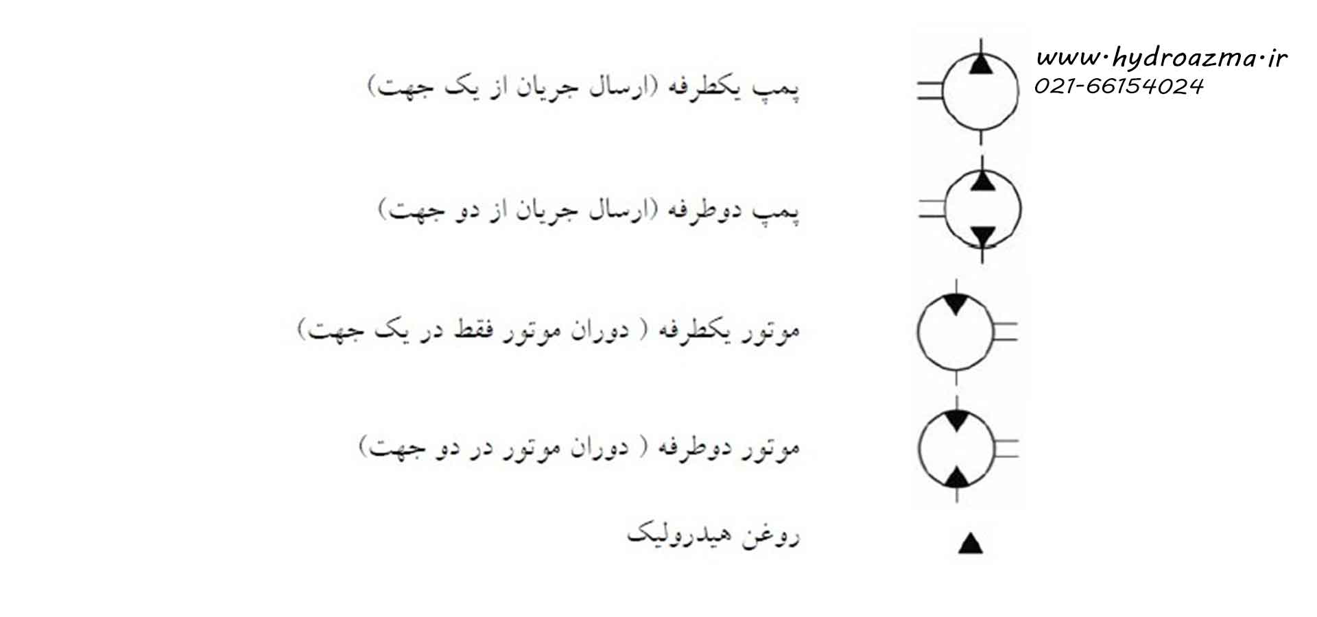
Pumps and motors
Hydraulic pumps and motors are represented by a circle, and the input or output power shaft is drawn along the circle as two parallel lines. The triangles inside these circles indicate the direction of the flow, which is outward in the pump and inward in the engine.
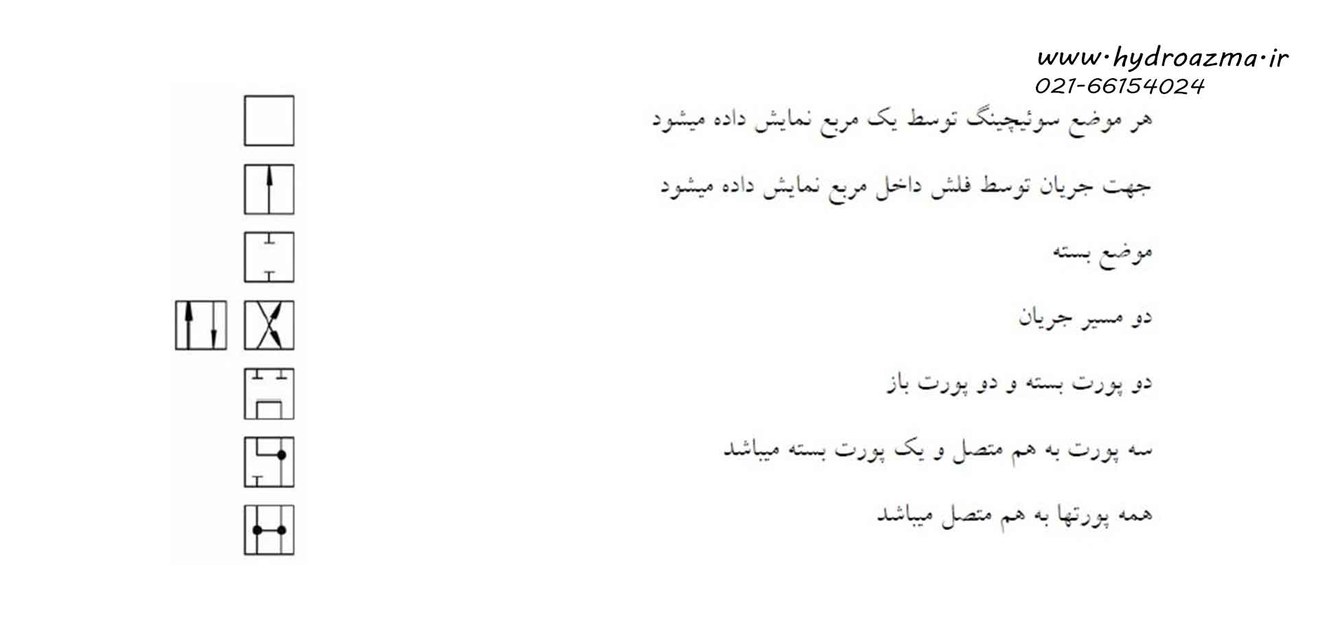
direction control valve
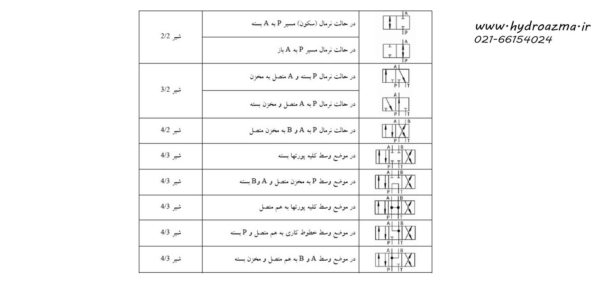
Direction control valves are represented by a number of connected squares. The number of squares indicates the number of valve switch positions. The arrows inside the squares show the flow direction. The vertical, horizontal and diagonal lines indicate how the valve ports are connected in the switched positions. When naming directional control valves, it is necessary to state the number of ports first and then the number of switch positions.
The switch positions of the direction control valves can be changed by various stimulation methods. The symbol of the lion is complete along with its stimulation method.
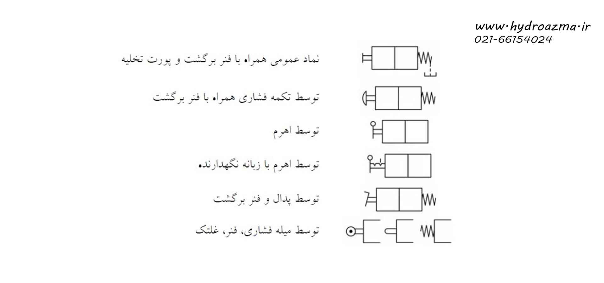
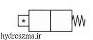
If a standard symbol is not used for stimulation, it is necessary to indicate the stimulation method with an asterisk and provide the necessary information in the description section. The form of not using the usual methods to stimulate milk is given below.
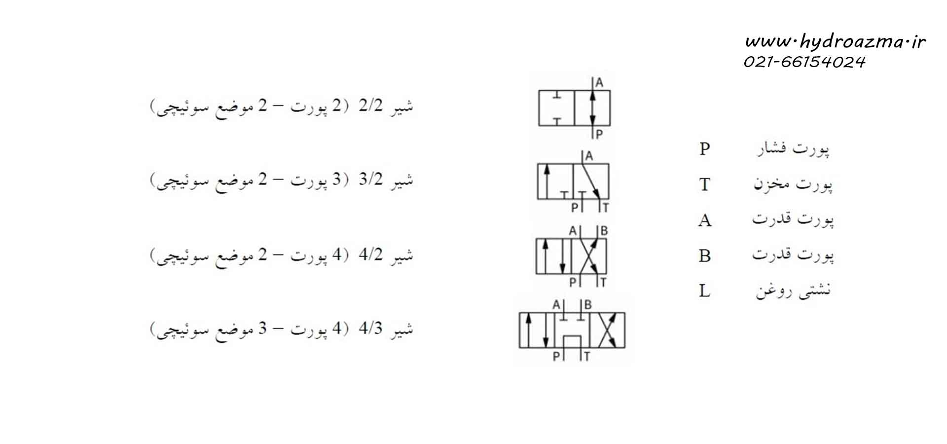
Some examples of direction control valves are presented below:
Pressure control valve
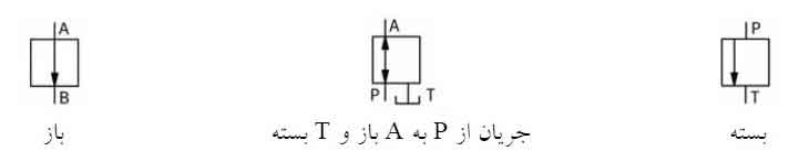
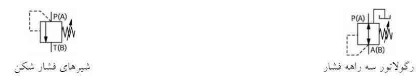
Pressure valves are represented by a square with an arrow indicating the direction of flow. Valve ports are marked with P (pressure port), T (reservoir port), or A or B. The position of the arrows inside the square indicates that the valve is normally open or closed.
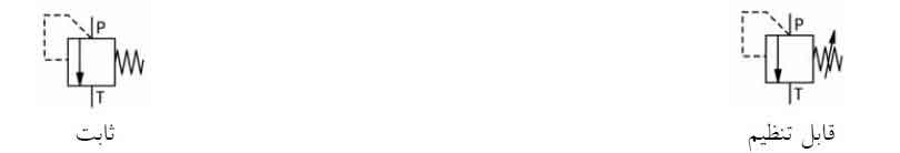
The other difference between pressure valves is whether they are adjustable or fixed, which is indicated by a diagonal line in the first case.
Pressure control valves are divided into two categories: relief valves and pressure regulator valves. The valves of the pressure relief group are closed in the normal position and the pilot pressure is taken from the inlet. This is while the pressure regulator valves are open in normal mode and the pilot pressure is taken from the outlet.
Flow control valve
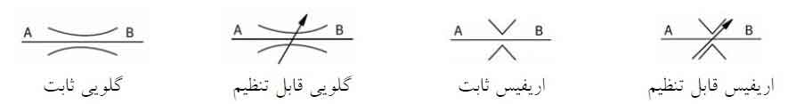
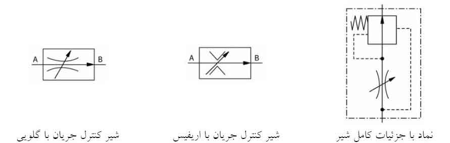
When it comes to flow control valves, there is one main difference between the valves. Valves that are not affected by changes in viscosity are called orifices, and valves whose performance is affected by changes in viscosity are called throats.
Check valve
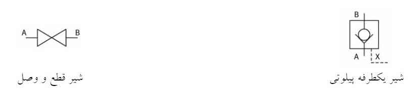
The symbol of one-way valves is a sphere on the flow sealing seat. The placement of this ball is in the form of an open angle. The tip of the open angle shows the direction of the closed flow.
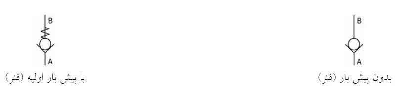
The symbol of one-way valves with pilot function is shown as a one-way valve inside a square. The valve control pilot is drawn with a line below this square. Disconnect and connect valves are drawn as two triangles facing each other. These valves are usually used to drain the oil tank or discharge the accumulator pressure.
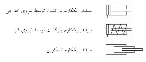
Cylinders
Cylinders are classified into two categories, single-acting and double-acting. Single-acting cylinders have only one port, that is, only the surface of their entire diameter is subjected to hydraulic pressure. These cylinders return under the influence of external forces such as weight force or spring force.
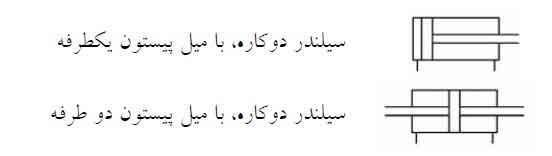
Double-acting cylinders have two oil inlet and outlet ports through which the oil is transferred to the front and back of the piston and the cylinder moves. In single sided double cylinders, the piston rod is only on one side of the cylinder, while in the double sided cylinder, the cylinder has two piston rods located on both sides.
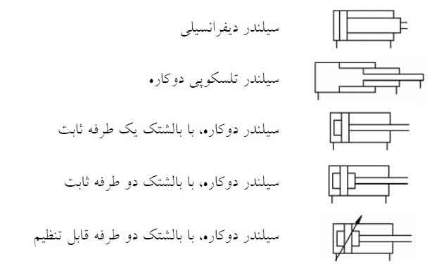
In the differential cylinder, the surface of the piston is twice the annular surface of the front of the piston. The symbol of this cylinder is distinguished from other cylinders by adding two parallel lines in front of the piston shaft.
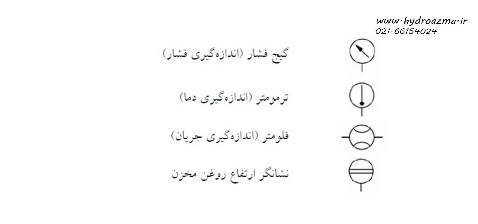
Sensors and instrumentation
Measuring devices for temperature, pressure, flow, etc. are shown in the hydraulic circuit with their own symbols.
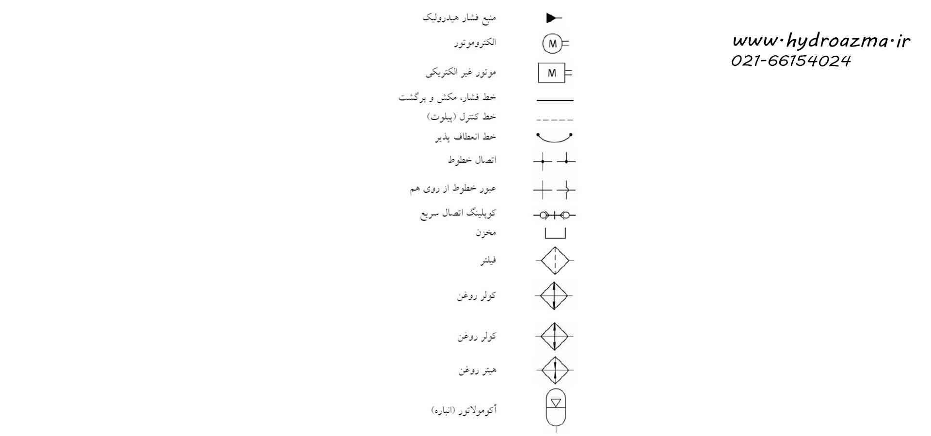
Energy transfer and oil preparation
The following symbols are used to show energy transfer devices and oil preparation in the hydraulic circuit:
Leave a Reply